The purpose of this assignment was to learn about proper mission planning when it pertains to flying a UAV. To do this, C3P Mission Planning Software was used which ensures a safe and effective UAV flight plan. Throughout this assignment, all of the proper steps to planning any UAV mission will be discussed as well as potential issues and solutions to using the C3P Mission Planning software.
Methods
Mission Planning Essentials
The first step in planning any UAV mission is to examine the study site. By looking at maps, 3D models, or, better yet, physically going to the site, the pilot can make note of any potential hazards such as power lines, radio towers, buildings, terrain, and crowds of people. It is also important to note whether there will be wireless data available or not. If not, then the pilot will need to cache the data obtained from the flight. Once observation has taken place and potential hazards/obstacles are noted, the pilot can now start to plan the mission. Using any geospatial data available and drawing out multiple potential mission plans (using C3P Mission Planner in this case) is best practice. Then, checking that the weather is suitable for flying a UAV and ensuring that all required equipment is fully charged and ready to go are the last steps required before the pilot is well prepared for the mission.
Once the pilot is ready to depart, a final weather and equipment check should be done. If the forecast appears suitable for a UAV flight and all of the necessary equipment is packed, the pilot is prepared to head out to the site.
At the site, before the pilot is ready takeoff a few final steps should be completed; the first being site weather. The pilot should document the wind speed and direction, temperature, and dew point of the study site. From there, the pilot should assess the field's vegetation; terrain; potential electromagnetic interference (EMI) from power lines, underground metals/cables, power stations, etc; and launch site elevation. Lastly, the units the team will be working in should be established and standard throughout the project thereafter, the mission/s should be reevaluated given any unforeseen characteristics of the site, the network connectivity should be confirmed, and all field observations should be documented in the pre-flight check and flight log.
Once all of these steps have been completed, the pilot is ready to fly.
Using the C3P Mission Planning Software
The first step to create a mission plan in C3P is to relocate the "home", "takeoff", "rally", and "land" locations to the study site on the map. Next, the user will draw a flight path using the draw tool. Depending on the individual site, the user can draw the path by point, line, or area. The tool also has a measurement option for precise flight path drawing. Once the user has drawn the flight path, the mission settings are adjusted. The mission settings include altitude, UAV speed, frontal and side overlap, ground sampling distance (GSD), overshoot, and camera type (figure 1).
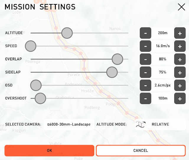 |
| Figure 1: Mission plan settings. |
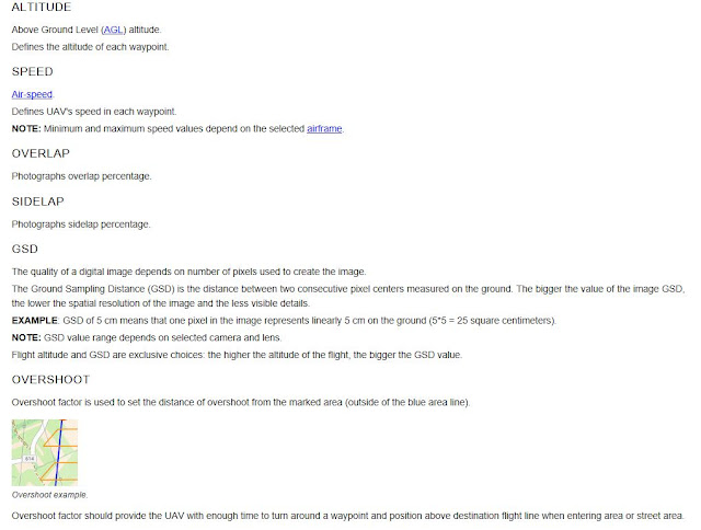 |
| Figure 2: More about the mission settings from the C3P help bar. |
After the user has drawn their flight area and has adjusted the settings, it is important to look at the map view and the 3D View to ensure the most effective flight path orientation is being used and that there aren't any obstructions in the flight path.
Figures 3 and 4 show two different orientations of the same flight path. The orientation is relative to each flight, but these images help to show the orientation of any flight plan can be adjusted. To do so, the boarder with the desired direction of flight is selected (the yellow boarder in figures 3 and 4).
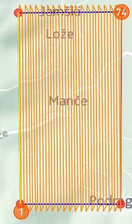 |
| Figure 3: Vertical Orientation |
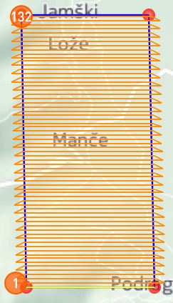 |
| Figure 4: Horizontal Orientation |
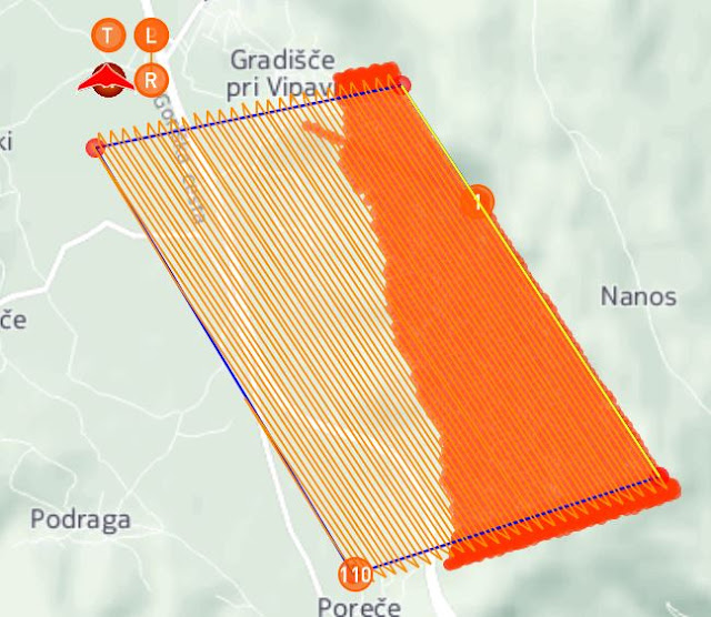 |
| Figure 5: Map view showing a problematic mission plan using absolute altitude. |
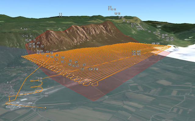 |
| Figure 6: 3D view of the same mission plan. |
Figures 7 and 8 show a corrected version of the flight path in figures 5 and 6, by using relative altitude instead of absolute. Notice how there are no red-orange areas demonstrating obstructions to the flight path in figure 7.
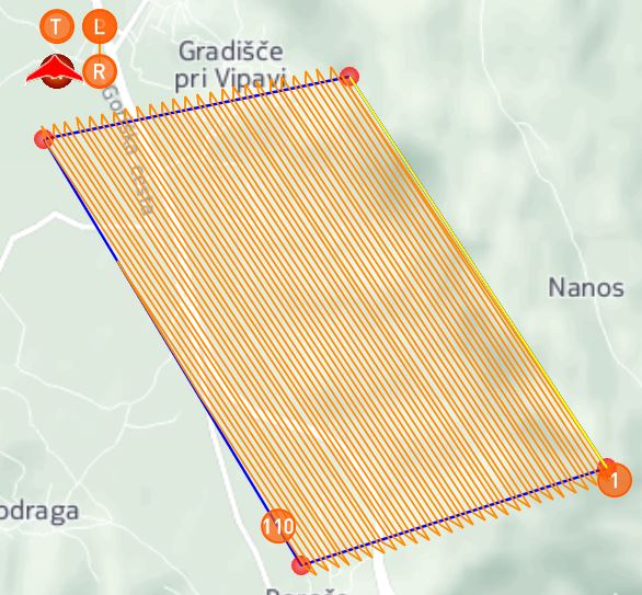 |
| Figure 7: Map view showing acceptable mission plan using relative altitude. |
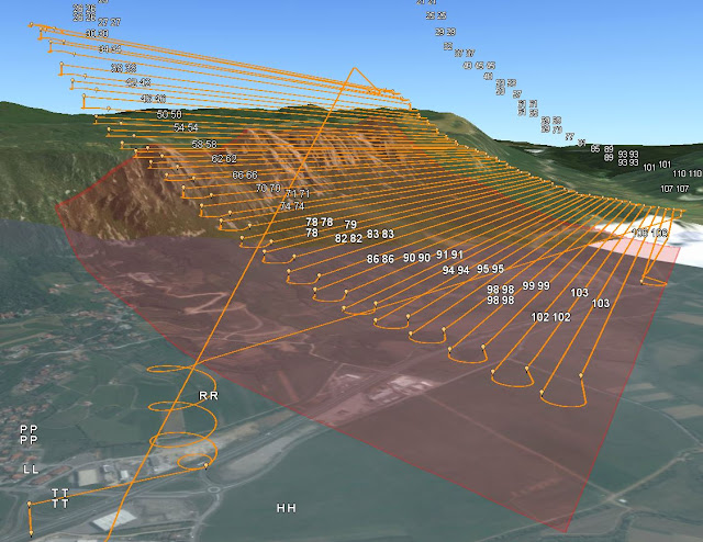 |
| Figure 8: 3D view showing same mission plan. |
Another thing to look out for is altitude itself. When the user is ensuring that the flight is within FAA flight zone regulations and/or using absolute altitude, the flight height might require adjustments. In figures 9 and 10, the flights cover the same area. Notice in figure 9, the flight is obstructed by the hill in the far right corner and is set to and absolute altitude of 200 meters. In figure 10, however, the flight has no obstructions and was raised to an absolute altitude of 350 meters.
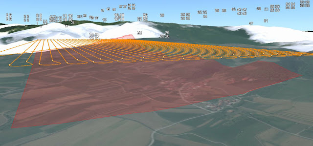 |
| Figure 9: 3D view of flight path set to 200 meters. |
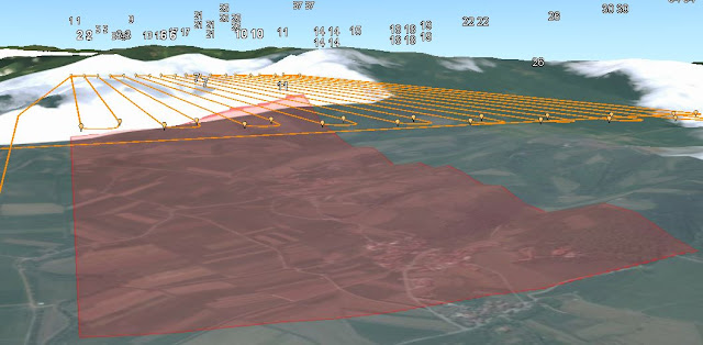 |
| Figure 10: 3D view of flight path set to 350 meters. |
Mission Planning Examples
Now that the user is comfortable with the software, two missions are created. One of which covers a road in Slovenia near the C3P default Baramor Test Field, and the other covers Mt. Simon and the Chippewa river in Eau Claire, Wisconsin.
The first mission planned (figures 11 and 12) covers about 8 kilometers of a road in south west Slovenia. This path was drawn using the streets (line) draw tool and the home, takeoff, rally, and land points were all placed at the same end to ensure minimal travel distance from take off to landing. The relative altitude was set to 200 meters.
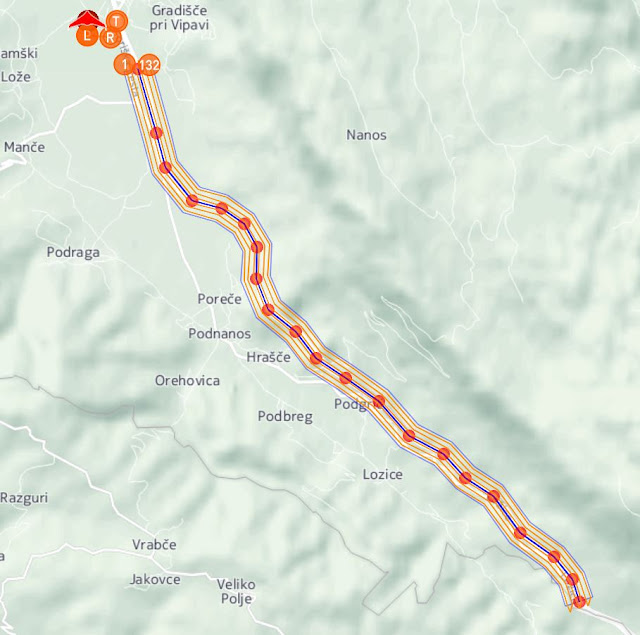 |
| Figure 11: Map view of road flight. |
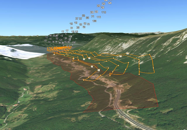 |
| Figure 12: 3D View of road flight. |
A second mission (figures 13, 14, 15, and 16) was created and covers roughly 581,000 square meters of the Chippewa river and surrounding bluffs in Eau Claire, WI. This path was drawn with the area draw tool and relative altitude was set to 300 meters.
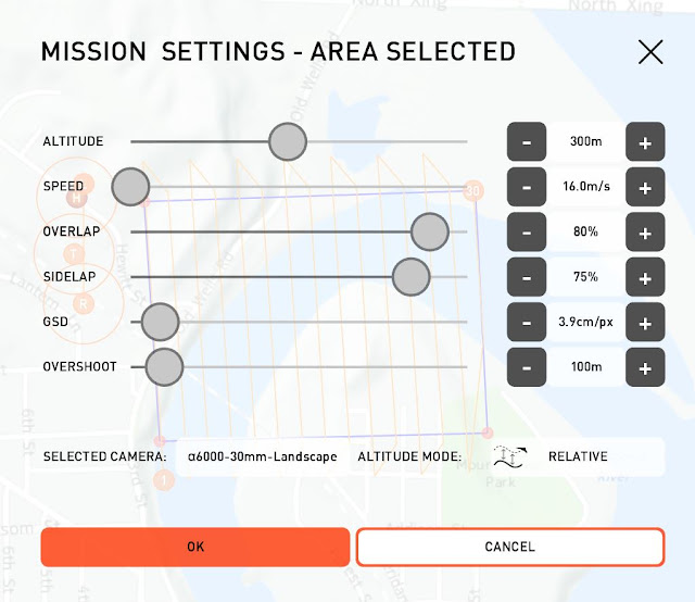 |
| Figure 13: Mt. Simon mission settings. |
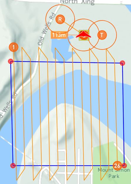 |
| Figure 14: Map view of mission plan. |
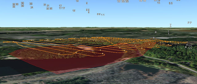 |
| Figure 15: 3D view of mission plan. |
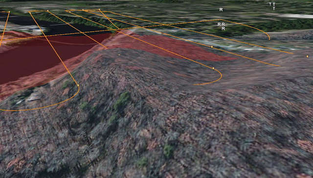 |
| Figure 16: Close up of flight path obstruction in 3D view. |
Although the mission altitude was set to be relative, there was an obstruction in the flight path (shown in figure 16) as well as no altitude variance throughout the mission plan (shown in figure 15). There are also no red-orange obstruction indicators in the map view. This is obviously problematic and could potentially mislead a user into thinking the mission plan would work when in actuality, it wouldn't. Again, it is important to verify the flight path in 3D viewer just in case an error like this occurs.
Discussion
Overall, the C3P Mission Planning software was extremely easy to use and can really help remote pilots in planning missions. I found that the user help guide was very easily navigable and helpful in understanding the software. The ability to set the wind speed and simulate the flight can provide the user a fairly accurate flight time and insight for path adjustments, assuming that other weather characteristics are suitable for flight. Also, having the software connect to ArcGIS Earth was very useful in validating the mission plan and seeing the flight path as you would in the field. I'm not sure, however, why the relative altitude setting was ignored by the software in flight two. It might have something to do with the spatial reference or system of measurement (imperial vs metric), but I really don't know. Another downside to this software is the flashing sensor calibration and upload way-points indicators. They are set up to stop the user from initializing the flight simulator before calibrating the sensor and uploading the waypoints. I found them to be a bit distracting when using the software and would prefer if there was a warning pop-up window, telling the user to ensure that the waypoints are uploaded and the sensor is calibrated.
No comments:
Post a Comment